Stack: Unity 2021.3, Universal Render Pipeline (URP), Visual Effect Graph
Note: Currently, Visual Effect Graph is production-ready only for HDRP. It’s still in development for URP so it’s possible you may encounter bugs. However, I have used it successfully with URP and have only noticed minor – not game breaking – issues.
This guide will show how to create the following effect:

This is the effect that I created for the game that I am working on. Previously, I had only worked with the old Particle System. This is the first effect that I created in the Visual Effect Graph and I encountered a few issues that took me a while to solve. I hope this tutorial will help you so that you won’t waste as much time as I did.

(The white dots are some weird GIF artefact, sorry about that.)
What is covered in this guide
- Step-by-step instructions on how to create an effect in the Visual Effect Graph that places footprints as decals.
- Footprints will follow along the player’s path and have the same direction as the player.
- Footprints will be placed based on the distance that the player traveled. It is possible to place footprints only in places where the feet really touch the ground. This is, however, not part of this guide.
- We will assume here that both left and right footprints are the same texture.
Prerequisites
- Unity project set up with the URP. HDRP might work too, but I haven’t tested it.
- Visual Effect Graph package installed in the Package Manager.
- Texture with a footprint. You can make your own or grab the one I made in Krita:

Step 1. Create a new VFX graph
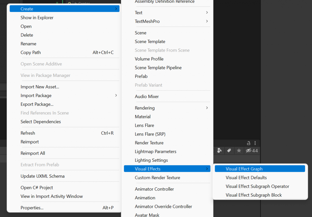
In your project window, create a new Visual Effect Graph asset:

If you don’t see it, you likely don’t have a Visual Effect Graph package installed.
Step 2. Add a Visual Effect component to the player
Go to your Player game object and add a new Visual Effect component. To Asset Template assign your Visual Effect Graph that you created in Step 1.

Step 3. Set up the base effect
Open your Visual Effect Graph. Unity created a basic effect for us, but it has a bunch of blocks that we don’t need.
Footsteps will spawn only when the player moves. Therefore, in the Spawn node remove the Constant Spawn Rate block and add a Spawn Over Distance block:

Footprints won’t have any velocity, so from the Particle System node remove the Velocity block.

While we are here, change the space from Local to World in the Initialize Particle node:

Remove the whole Output Particle Quad node:

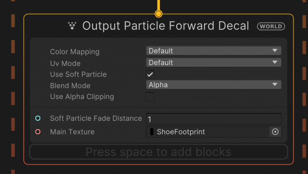
Instead of quads we will use decals. Create a new Output Particle Forward Decal node and attach it to the Update Particle node. Also, change the space from Local to World on both Update Particle node and Output node.

Step 4. Place footsteps under the player
The footprints should exist in the world space, not the local space. But inside the graph, we only have access to our local position. We need to translate it into the world position. Basically, we want to know what’s the world space equivalent of our local (0,0,0) position.
To do this, create a new block called Change Space, set Target Space to “World”, set the input space to “L” which means “Local”, and leave the values as they are.
Link the output to the Position in the Spawn node:

Step 5. Rotate the footprints so they match player’s rotation
First, create a Set Angle block. In this case, we only need to change two angles: X and Y, so select Channels accordingly:

By default, our footprints will be projected along the global Z (forward) axis, instead of lying flat on the ground. So we need to rotate them 90 degrees around the X axis to make them horizontal. Go ahead and create a new Vector3 block and set X to 90. Connect the Vector3 block to the Set Angle.XY block:

The Y axis is more complicated. The rotation around the Y axis depends on the player’s rotation. If the player is rotated to the right, then footprints need to be rotated to the right. If the player is facing to the left, then footprints need to match as well.
So, to rotate footprints we need to get the player’s rotation in the graph. We will do it by creating a property to hold the Player’s Transform. Open the graph’s Blackboard if it’s closed and press the “+” button to add a new Transform property. Rename it to “PlayerTransform”:

Now we need to make sure this property’s value is bound to the Player’s transform. Go back to your Player game object where you added the Visual Effect component. Add a new component called VFX Property Binder. Fill in the property name (PlayerTransform) and assign the Transform component. It should look like this:

Our property PlayerTransform holds the Player’s Transform component. We now have access to the Player’s Transform in the Virtual Effect Graph.
Go back to the graph and drag the property to the graph so that it creates a block. Expand “angles” because that’s what we need:

We only need the “y” angle because this is the (vertical) axis around which we need to rotate the footprints. Get the “y” value and link it to our “y” value in the Vector3 block we created previously. The entire section should look like this:

Step 6. Place one foot to the left and the next one to the right
In Step 4, we calculated the world position of our footprints. Now, we need to use the calculated position to let the particles know they must use that position. Usually you could use a Set Position block to set the particle’s position. But if we did that, then all footprints would just be placed in a straight line like so:

That doesn’t look good. What we want is to have every second footprint slightly to the left, and every second footprint slightly to the right.
We will use a block that lets us specify the list of points where the particles are to be positioned. There will be a point for the left foot slightly to the left from the center, and a point for the right foot slightly to the right from the center.
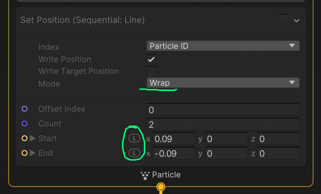
In the Initialize Particle node, add a block called Set Position (Sequential: Line). Our list has only two points: one for the left foot and one for the right foot. Change the X values to move the points to the left and to the right. Change the space from world space to local space for each point because we are calculating the offset based on our centre in local space.
Set the Mode to Wrap so that when the particle system uses up all the points from the list, it will start over from the beginning. The first footprint will get the first point from the list, the second footprint will get the second position, the third footprint will again get the first point, and so on.

Step 7. Fade footprints over time
To the Particle Update node, add a block to fade alpha over life:

Adjust the Alpha curve to achieve the desired effect.
Step 8. Assign the footprint texture to the Output Particle Forward Decal node

The end
And that’s it. You now should have working footprints.
You might also need to add a Set Size block to the Initialize Particle node unless you have the footprint texture of exactly the right size.
If you have any issues following this guide, please let me know so that I can improve it. My email is [email protected] and my Twitter is @JustynaDorsz.